I'm pretty sure my inspiration for this project was Boston Dynamics's Big Dog.
I think the idea was to see just how cheaply I could build a walking quadruped.
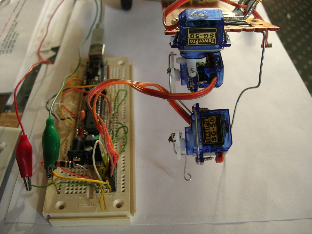
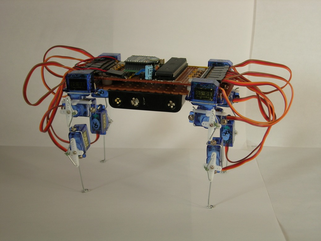
Small inexpensive servos linked together with bent paper clips.
In 2008 I bought a few small servos and started playing with them
using an Adafruit Boarduino (ATmega168) previously purchased to learn about the Arduino platform.
I decided my robot's legs would need 3 servos apiece: hip, knee, and
(because I envisioned it being able to turn while walking) rotate.
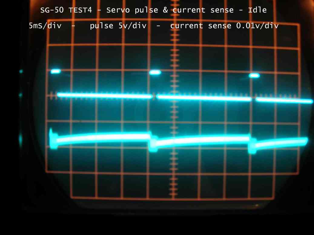
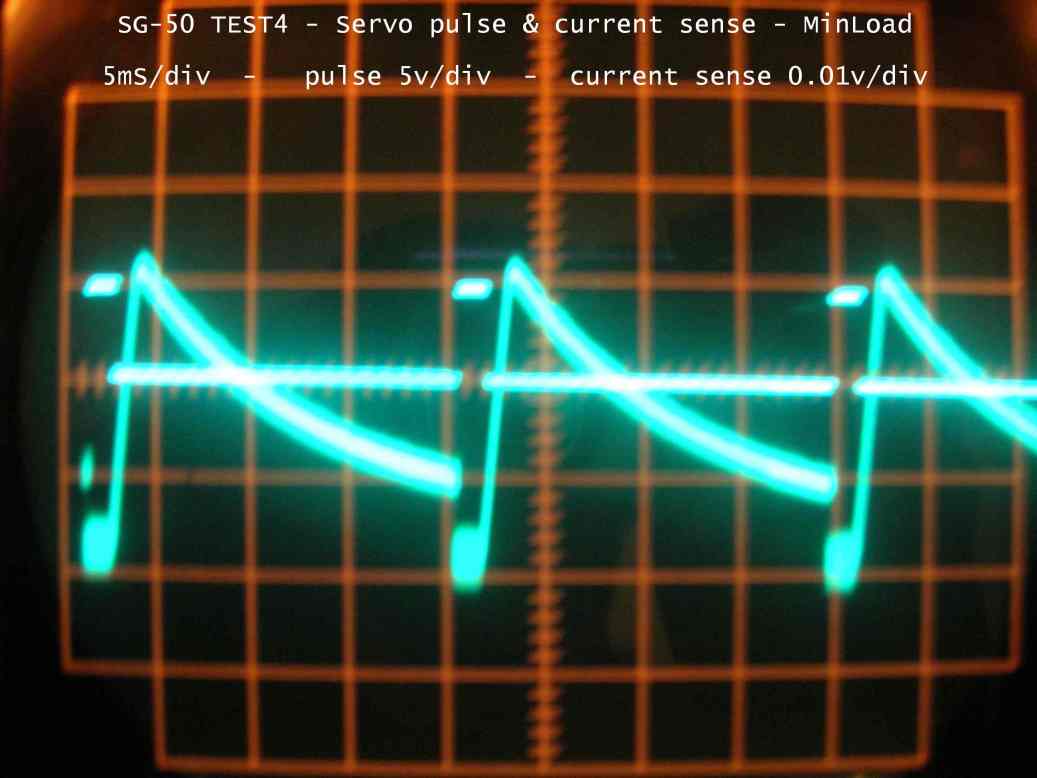
I also thought it would be a good idea to have the servos error signal available.
It would give me an indication of how much force the servo was exerting.
Most hobbyist servos don't expose it, but I thought I could get an approximation
of a servo's error by sensing its current draw.
Testing proved the idea; I could get the magnitude of the error, but not it's direction.
(Unless I remembered which way I'd been asking the servo to travel.)
The Arduino platform was unsuited to my needs.
so I switched to the AVR toolchain under Cygwin.
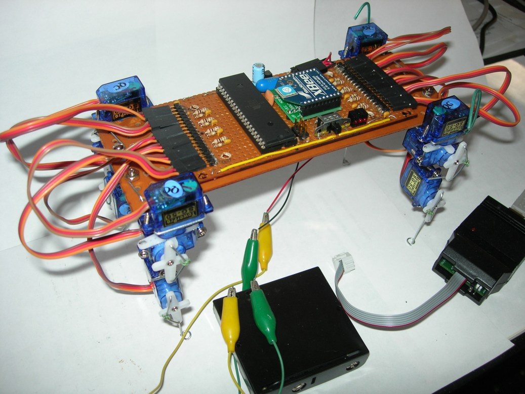
I ordered more servos and a microcontroller with more IO: an ATmega644.
I also bought a pair of XBee radio modules to allow wireless control.
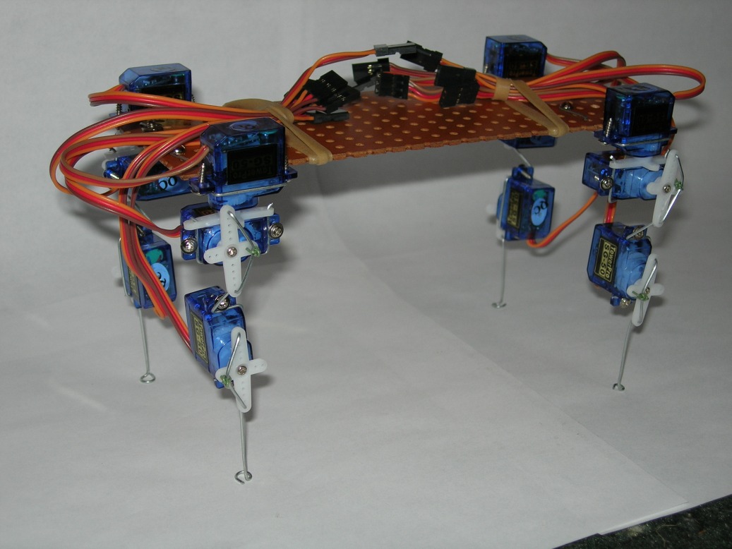
When the servos arrived I assembled the other 3 legs with more paper clips and,
using a piece of perf board as a backbone, the robot's skeleton.
I was ready to go wireless and resume testing.
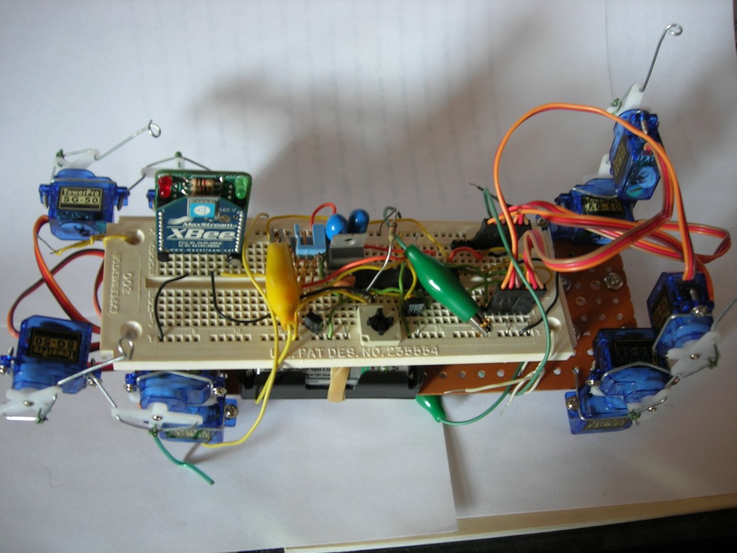
My solderless breadboard circuit (with the ATmega168) was capable of controlling 2 legs.
I added one of the XBee radios to it and attached both it and
a holder with 4 AA NiMH rechargeable batteries to the bottom of the perf board.
It would control the "front" legs.
The rear legs would be raised out of the way
and that end of the robot suspended from a ridiculous set of wheels
I made from 4 plastic plates and wooden skewer.
Despite an alarming amount of stagger and wobble, it managed to drag itself forward.
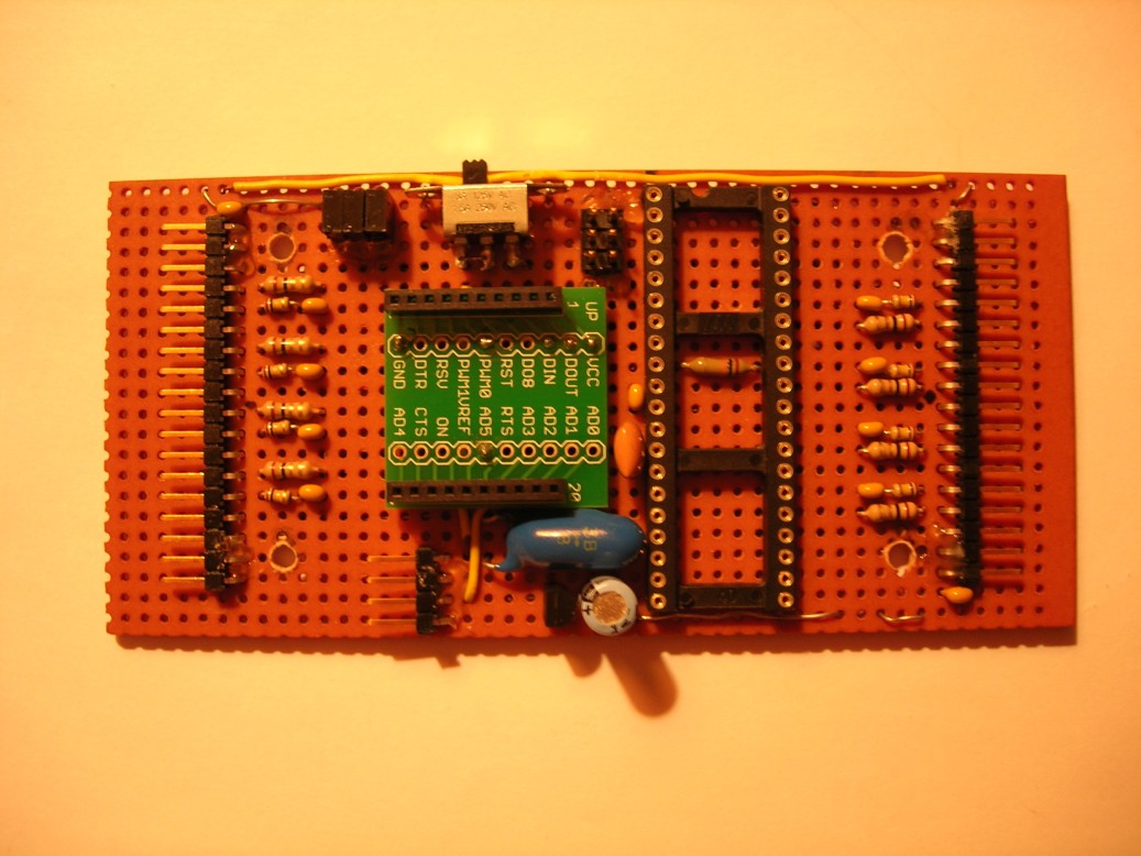
Encouraged, I proceeded ahead with the design and construction of the ATmega644 circuit.
Limited to 8 analog inputs, I decided I could do without error sensing on the rotate servos.
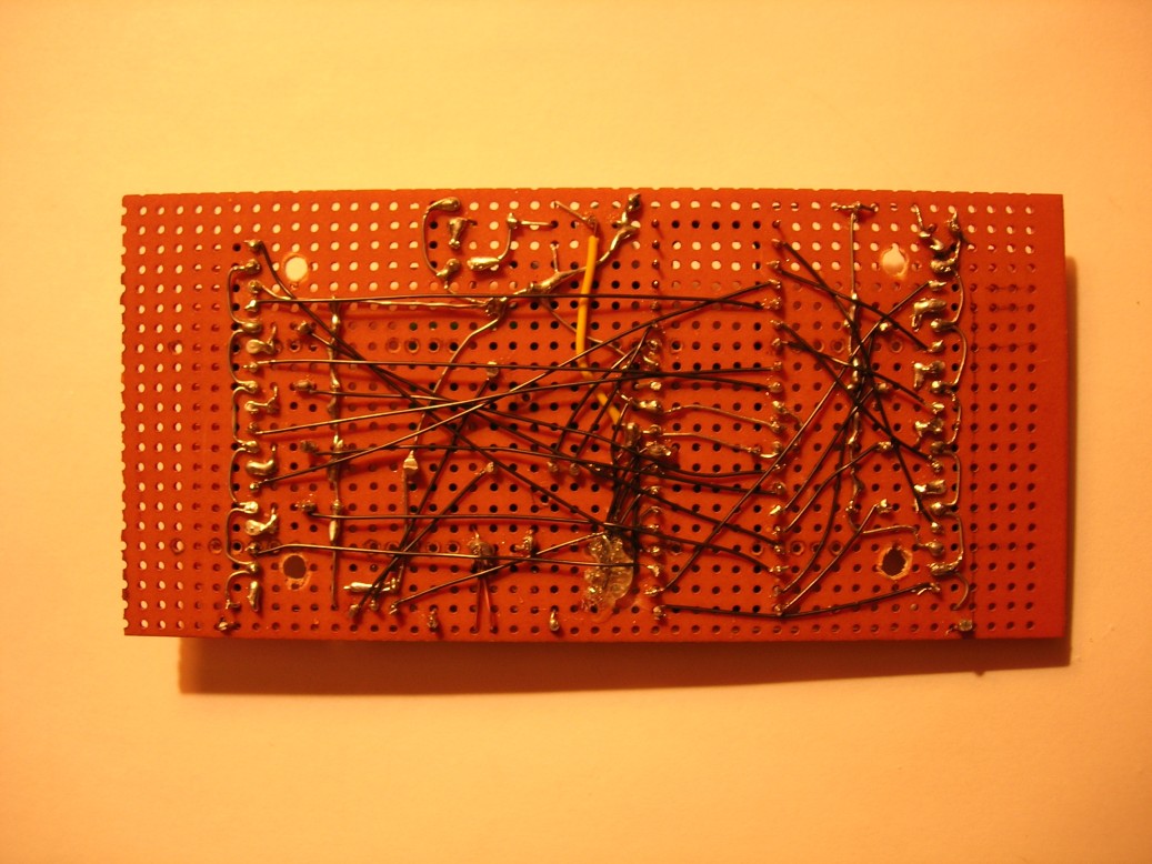
I decided it would be quicker and easier to wire the new controller point-to-point
(using primarily wire-wrap wire)
rather than designing, fabricating and assembling a printed wiring board.
The software is far from finished - and,
since the robot has been packed away and untouched for a decade, may never be.
It accepts user-unfriendly commands over the XBee-provided serial link.
No servo (or leg) positions are hard coded; there is storage for 10 leg positions
(30 servo positions shared by all legs)
and a positional offset (trim) for each of the 12 servos.
There are commands to set and display the leg positions and offsets
as well as to save and recall them from eeprom.
The walk command simply continuously cycles the legs through positions 0-5,
varying phase and direction by leg.
The last version of the source code is here: test.c.
Missing are 3 include files which I believe were part of the AVR toolchain installation.
This document shows the leg positions used and phasing for the walk:
walk.pdf.
Maybe I'll get back to it someday (probably with sturdier legs) but...
Hey! I got it to walk.